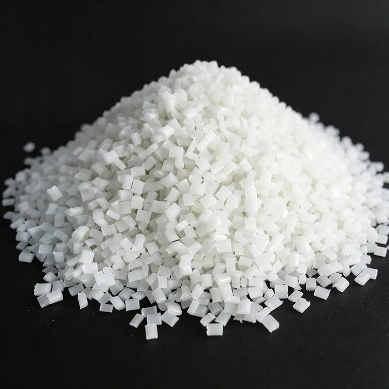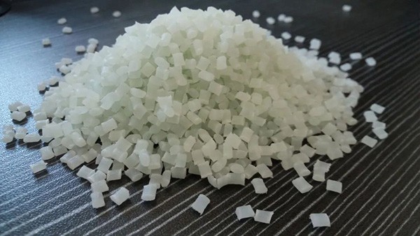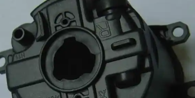
PA6 GF30 Warpage: 9 Injection Molding Adjustments That Actually Fix It
A flat plaque that comes out of the mold looking like a potato chip — that is warpage, the most complained-about dimensional defect in glass-reinforced nylon. With 30% glass fiber, PA6 becomes stiffer and stronger, but it also becomes anisotropic: it shrinks differently along the flow direction and across it, and that difference is what bows and twists the part. Most warpage problems can be reduced dramatically with machine adjustments, before you touch the mold or the material. Here is the order we work through them on the shop floor, with parameter ranges from real production trials.
Table of Contents
1. What Does Warpage Look Like, and How Do You Measure It?
Warpage shows up as bowing or twisting: the part does not sit flat, corners lift off the table, or assembly gaps appear. It is not the same as shrinkage (overall size change) or sink marks (local depressions) — it is a shape deformation. The usual check: put the part on a surface plate, measure the gap with a feeler gauge at the corners and along the diagonals, and record the highest number. Large flat panels, open frames, and thin ribs next to thick bosses are the worst offenders. On glass-filled parts, the deformation is rarely random — it usually follows the direction the material flowed in the mold.
2. Why Does PA6 GF30 Warp? (Understand This First)
The number one cause is fiber-orientation anisotropy. During filling, glass fibers align along the flow direction. Shrinkage in the flow direction is small (roughly 0.3–0.5% at 30% GF), while shrinkage across the flow direction stays high (roughly 0.9–1.1%). The gap between the two is the driving force of warpage. If fiber orientation is uneven across the part — longer flow paths, thin ribs, gates in one corner — different zones shrink by different amounts, and the part bends.
The second cause is uneven cooling. PA6 is semi-crystalline: the cooling rate decides crystallinity, and crystallinity decides shrinkage. If the core and cavity run at different temperatures, or one zone cools faster than the rest, one side shrinks more than the other and the part bows toward it. Third comes uneven packing: under-packed zones shrink more, and if those zones sit next to well-packed ones, you get distortion.
So every adjustment below attacks one of two things: make the shrinkage difference smaller, or make fiber orientation more uniform. Keep that in mind and the parameter changes stop looking random.
3. Nine Adjustments, in the Order We Try Them
3.1 Balance the mold temperature (step one)
Run PA6 GF30 at 80–100 °C, and make it uniform. Core and cavity should be within roughly 5–10 °C of each other — a hot core with a cold cavity bows the part toward the hot side every time. Check the mold temperature controller, look for dead spots in the water channels, and use the upper end of the range (100–120 °C) for thick parts so cooling slows down and crystallization evens out.
3.2 Extend cooling time and make cooling uniform (step two)
Parts ejected too hot keep warping on the bench. Increase cooling time until the part holds its shape after demolding; 20–40 seconds is normal for a flat panel, and more for thick sections. Balanced water channels matter more than you think — if one zone cools faster, that zone shrinks more. Do not open the mold early to save cycle time; you will pay for it in rework.
3.3 Set holding pressure and time properly (step three)
Under-packing is a quiet warpage driver: the last-filled zones shrink more. Raise holding pressure until the part stops gaining weight (a sign the gate is sealed), and keep holding until the gate freezes. Multi-stage holding — high pressure first, then a lower step — packs the thick sections without over-packing the gate area. If one side of the part warps consistently, check that all cavities receive the same hold pressure.
3.4 Adjust the injection speed profile (step four)
High injection speed increases fiber orientation along the flow, which feeds anisotropy. For warpage, moderate the fill and use a staged profile: slow start at the gate to avoid jetting, steady middle, slow before switch-over. There is a trade-off with floating fiber — which prefers a fast fill — so find the balance for the part in front of you.
3.5 Review gate position and flow direction (step five — a big one for fiber parts)
Fibers align with the flow, so the flow direction controls the shrinkage direction. If you can, gate so the main flow runs along the part's long axis. For large flat panels, a center gate or multiple gates shortens the flow and evens out the orientation. Avoid long flow paths and unbalanced fills from a gate in one corner. This is covered in more detail in our glass fiber content selection guide, where the rule is the same: shorter, more balanced flow means less anisotropy.
3.6 Even out wall thickness and use ribs (step six)
Thick sections shrink more than thin ones, and the transition zone between them is where warpage starts. Even out wall thickness where you can, avoid abrupt changes, and add ribs to stiffen large flat areas — a ribbed panel warps far less than a plain one at the same stiffness. Keep the gate in the thickest section and keep the flow length reasonable (at 1 mm wall, try to stay under roughly 80 mm for 30% GF).
3.7 Anneal the part when precision matters (step seven)
Post-mold annealing relieves internal stress and stabilizes dimensions. For PA6, 130–150 °C for 1–2 hours in a circulating-air oven, then slow cooling in the oven, works well. It is not practical for every high-volume run, but for precision parts — and for parts that warp more after a week of storage or during machining — it is often the fastest fix. See our nylon processing guide for the full drying and handling routine that keeps the material stable before molding.
3.8 Check ejection (step eight)
Uneven ejection force deforms the part as it leaves the mold. Use more ejector pins or larger contact area, position them symmetrically, and make sure the part is cool enough before ejection. If the part is soft when it comes out, no amount of later tweaking will hold the shape.
3.9 Change the material (step nine, last lever)
Drop to 25% GF instead of 30% if the mechanical spec allows — less fiber, less anisotropy, less warpage.
Switch to a mineral-filled or glass-plus-mineral hybrid grade. Minerals are nearly isotropic and fight warpage while keeping stiffness — the classic fix for flat housings.
Consider a PA6/PA66 copolymer or a grade formulated for low warpage; several suppliers make them specifically for large flat parts. If you are comparing PA6 GF30 against PA66 GF30, our GF30 comparison shows where the differences actually matter.
4. Quick Parameter Reference for Warpage Control
| Parameter | Typical range | Note |
|---|---|---|
| Drying | 80–90 °C × 4–6 h, dehumidifying dryer | Moisture ≤ 0.1% before molding |
| Mold temperature | 80–100 °C, uniform | Core/cavity within ~5–10 °C; 100–120 °C for thick parts |
| Melt temperature | 250–270 °C | Per grade datasheet; keep below ~300 °C |
| Injection speed | Moderate, staged profile | Too fast increases fiber orientation |
| Holding pressure | Adequate + multi-stage | Hold until gate seals; check part weight |
| Cooling time | Until part stable after demolding | 20–40 s typical for flat panels |
| Annealing | 130–150 °C, 1–2 h, slow cool | Precision parts; relieves residual stress |
5. A Real Case From the Shop Floor
A customer molds a flat battery cover, about 200 × 120 mm, 1.5 mm wall, in black PA6 GF30. Parts came out bowing 3–4 mm in the middle. The mold ran at 70 °C, gate on one short edge, single-speed fill, 25 s cooling. We made five process-only changes, in order: (1) mold temperature up to 95 °C and both halves balanced; (2) cooling time from 25 s to 40 s; (3) injection speed reduced about 20% with a three-stage profile; (4) holding pressure up about 20% and hold time extended until part weight stopped changing; (5) annealed the first batch at 140 °C for 2 hours to prove the fix. Bowing dropped from 3–4 mm to under 0.8 mm, and to under 0.3 mm after annealing. The customer shipped without rework. The lesson: warpage is a differential-shrinkage problem, and you solve it by making the shrinkage uniform — not by clamping the part harder.
6. Common Mistakes That Make It Worse
Opening the mold early to save cycle time — the part warps after ejection, then gets blamed on the material.
Running a fast fill "because it fixed floating fiber" — high speed increases fiber orientation and makes warpage worse.
Ignoring the temperature difference between the two mold halves — one side always shrinks more.
Under-packing the end of fill while over-packing the gate zone — distortion follows.
Choosing 40–50% GF for "more stiffness" on a flat part — the most anisotropic choice you can make.
7. Frequently Asked Questions
Why does PA6 GF30 warp more than unreinforced PA6?
Because the glass fibers align along the flow direction and create anisotropy: flow-direction shrinkage is small, cross-direction shrinkage stays high. The bigger the gap, the more the part bends. Unreinforced PA6 shrinks almost equally in all directions, so it warps far less.
Does raising the mold temperature reduce warpage?
Usually yes, if both halves are balanced. A higher, uniform mold temperature slows cooling, evens out crystallization, and relieves internal stress. The key word is uniform — a hot core with a cold cavity will bow the part toward the hot side.
Can annealing completely fix warpage?
Annealing at 130–150 °C for 1–2 hours removes most residual stress and stabilizes dimensions, and it helps a lot with warpage that develops after storage or machining. Orientation-driven warpage improves but is limited by the geometry and tooling. Do not rely on annealing to rescue a badly designed part.
Should I use less glass fiber to reduce warpage?
Dropping from 30% to 25% GF reduces anisotropy and warpage, at the cost of some stiffness and strength. Check the mechanical spec first. If stiffness must stay high, a glass-plus-mineral hybrid keeps stiffness and reduces warpage better than dropping GF alone.
Is warpage the same as shrinkage?
No. Shrinkage is a change in overall size; warpage is a change in shape, caused by differential shrinkage between zones or directions. You can have a part that shrinks the expected amount yet still bows badly.
Is mineral-filled PA6 better than glass-filled for warpage?
For warpage, yes — minerals like talc are nearly isotropic, so shrinkage is more uniform. The trade-off is lower strength and stiffness than glass fiber at equal loading, and different surface finish. Hybrids (glass + mineral) are the practical middle ground for flat housings.
8. Summary
In one sentence: warpage is differential shrinkage — balance the mold temperature, cool thoroughly, pack evenly, moderate fiber orientation with gate and speed, anneal when precision matters, and only then look at the material. Process first, mold second, material last. For the full family of glass-fiber nylon defects and their fixes, see our defect troubleshooting section.