Industry Application · September 12, 2026 · Juhai R&D Center
Modified PA6 in Low-Voltage Electrical Appliances — MCCB & Contactor Housings, Flame Retardant & Electrical Safety
Low-voltage electrical appliances — molded case circuit breakers (MCCB), contactors, relays and switches — live or die by their plastic housing. The material must hold a live copper busbar without cracking, extinguish an internal arc without igniting, resist tracking across its surface for decades, and survive 10,000+ mechanical operations. This article explains why modified PA6 is the dominant housing material in this industry, and walks through each performance requirement with the actual standard, test method and acceptance value a PA6 compound must meet.
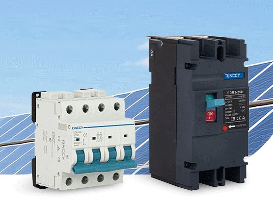
Table of Contents
1. Why PA6 Dominates Low-Voltage Electrical Housings
A low-voltage electrical housing is one of the most demanding applications for an engineering plastic. It sits inches from a live copper busbar carrying up to 1,600 A, and it must perform reliably for 10,000+ switching cycles over a 20+ year service life. The competing materials — PA6, PA66, PBT, ABS, PC/ABS — are often compared, but PA6 holds the largest share in molded case circuit breakers and contactors for four reasons:
Mechanical toughness: PA6 absorbs the shock of the spring-loaded operating mechanism in a breaker without cracking. Unreinforced PA6 has a notched Izod of ~4.5 kJ/m², and 30% glass-fiber PA6 reaches 12–17 kJ/m² — enough to survive the hammer-blow energy of a closing contactor armature.
Thermal stability at operating temperature: MCCBs operate continuously at 60–90°C internal temperature, with transient spikes to 130°C during overload. PA6 GF30 has an HDT of ~190°C at 1.82 MPa, giving a comfortable margin.
Flame retardant efficiency: PA6 is inherently V-2 (it drips and self-extinguishes) and can be raised to V-0 with a relatively low loading of flame retardant compared to ABS or PBT. The nitrogen in the amide backbone contributes to char formation.
Cost: PA6 is the lowest-cost polyamide, and its easy processing keeps the total part cost below PA66. For the millions of breaker housings produced annually, this cost gap is decisive.
The areas where PA6 gives ground to PA66 are long-term heat aging above 140°C and the highest CTI (600V) ratings. In practice, electrical OEMs split their design: PA6 for the main housing and operating mechanism, PA66 for the arc chamber and terminal shields that see the highest temperatures.
2. Inside an MCCB Housing — Where PA6 Is Used
A molded case circuit breaker is not one part — it is an assembly of 30–80 plastic components, each with a different material requirement. Understanding the component breakdown explains why "PA6 for MCCB" is not a single grade but a family of formulations.
| MCCB Component | Material Typically Used | Key Requirement |
|---|---|---|
| Upper & lower housing shells | PA6 GF30 FR (V0) | Flame retardant, CTI ≥ 300V, mechanical strength |
| Operating handle | PA6 GF15 (unfilled or low GF) | Toughness, cosmetic surface, color stability |
| Arc chamber side walls | PA66 GF30 FR or melamine-PA6 | Arc resistance, 200°C+ short-term heat |
| Terminal shields / line shields | PA66 GF30 FR V0 | CTI ≥ 600V, flame retardant |
| Crossbar / mechanism base | PA6 GF30 (non-FR or V2) | Dimensional stability, creep resistance under load |
| Contact support / moving contact carrier | PA66 GF30 heat-stabilized | Short-term 250°C+ resistance during short-circuit |
| Arc runner / deion grid support | Melamine-PA6 or PA66 mineral | High arc resistance, low burn-through |
The main housing shells are where PA6 FR GF30 is the workhorse. This article focuses on that component — the requirements and formulation that make a PA6 grade suitable for MCCB and contactor housings.
3. Flame Retardant Requirement — UL94 V0 & Glow Wire
Electrical appliances can fail, and when they do the failure often involves heat or an internal arc. The housing must not sustain a flame. Two standards govern this: UL94 (vertical burn) and the glow-wire test (IEC 60695-2).
UL94 V-0 at the housing thickness
UL94 measures a material's response to a small gas flame applied to the bottom of a vertically held bar. For an MCCB housing, the requirement is almost always V-0 at the actual wall thickness — typically 1.5–3.0 mm. The V-0 criteria are strict:
Afterflame time after each flame application ≤ 10 seconds.
Total afterflame time for all 10 flame applications on 5 specimens ≤ 50 seconds.
No burning drips that ignite the cotton indicator below.
No specimen burns up to the holding clamp.
Unmodified PA6 is inherently V-2 at most thicknesses — it self-extinguishes but drips flaming material. To reach V-0, a flame-retardant package is added. For PA6, the dominant commercial systems are:
Brominated polystyrene + antimony trioxide (halogenated): Effective at 12–18% total loading, gives V-0 at 1.0–1.5 mm. Lowers CTI to ~250–400V. Lower cost.
Aluminum diethylphosphinate (DEPAL) + melamine polyphosphate (halogen-free): Effective at 15–20% loading, gives V-0 at 0.8–1.5 mm. Maintains CTI ≥ 600V. Higher cost, preferred for EU and high-end electrical.
Red phosphorus (microencapsulated): Effective at 6–10% loading, gives V-0 at 1.5 mm. Dark red/brown color only. Highest CTI among PA6 FR systems (often 600V+).
Glow Wire Ignition Temperature (GWIT) — IEC 60695-2-13
The glow-wire test simulates a glowing wire (e.g., an overheated resistive element) touching the plastic surface. For unattended electrical appliances covered by IEC 60335-1, the end product must pass a glow-wire test at 750°C on the finished part, and the material itself is often required to have a GWIT ≥ 775°C to provide a safety margin. The test heats a nickel-chromium wire to the test temperature, presses it against the specimen for 30 seconds, and records whether ignition occurs and how long any flame persists.
PA6 FR grades using DEPAL or red phosphorus typically achieve GWIT 775–850°C, which comfortably passes the 750°C end-product requirement. Brominated systems may achieve GWIT 750–800°C depending on loading.
4. Tracking Resistance — CTI 600V (IEC 60112)
Tracking is the silent killer of electrical plastics. Over years of service, dust, humidity and surface contamination create a conductive path across the plastic between two live electrodes at different potentials. A leakage current flows, generating heat that carbonizes the surface — and the carbonized track becomes a short circuit that can ignite the housing.
The Comparative Tracking Index (CTI), measured per IEC 60112, quantifies this risk. A 0.1% ammonium chloride solution is dropped between two platinum electrodes on the specimen surface while a voltage is applied. The CTI is the maximum voltage (in volts) at which 50 drops can be applied without tracking or ignition. Materials are classified into Performance Level Categories (PLC):
| PLC | CTI Range (V) | Typical Application |
|---|---|---|
| 0 | ≥ 600 | High-voltage terminal blocks, MCCB terminal shields |
| 1 | 400 – 599 | General MCCB housings, contactors up to 400A |
| 2 | 250 – 399 | Small relays, switches, low-voltage accessories |
| 3 | 175 – 249 | Non-critical internal parts |
For MCCB housings, the industry requirement is typically CTI ≥ 300V (PLC 2) or ≥ 400V (PLC 1). The critical design decision is whether to use a halogenated or halogen-free flame retardant:
Brominated FR PA6: CTI drops to 250–400V because the bromine and antimony residues promote surface conductivity. This often limits the part to PLC 2.
Halogen-free FR PA6 (DEPAL or red phosphorus): CTI stays at 500–600V+ (PLC 1 or 0), because the phosphorus-based FR does not leave conductive residues on the surface.
This is why modern high-current MCCB housings and EV connector components increasingly specify halogen-free FR PA6 — not for environmental reasons alone, but because CTI 600V is a hard electrical requirement. Juhai's PA66 FR-V0 grade (CTI 600V, GWIT 775°C) is the reference for this performance tier; PA6-based equivalents are compounded to the same CTI target when customers prefer PA6 cost or PA6 processing.
5. Insulation & Arc Resistance
Beyond tracking, the housing must be a good electrical insulator and resist the direct hit of an electric arc.
Volume & surface resistivity
Per IEC 60093, the volume resistivity of PA6 GF30 FR is typically 10¹³ – 10¹⁵ Ω·cm and surface resistivity is 10¹² – 10¹⁴ Ω at 23°C / 50% RH. These values are well above the 10¹² Ω·cm threshold required for insulating materials in low-voltage apparatus. Note that PA6 is hygroscopic — at 90% RH, surface resistivity can drop by 1–2 orders of magnitude. Designs with tight creepage distances must account for humid-environment resistivity, not dry-lab values.
Arc resistance (ASTM D495 / IEC 61621)
Arc resistance measures how long a material resists the formation of a conductive surface path when exposed to a high-voltage, low-current arc. For PA6, arc resistance is typically 120–180 seconds. This is lower than melamine or PTFE-based arc-resistant plastics, but adequate for MCCB housings where the arc is contained within the arc chamber, not on the housing interior surface. For parts directly exposed to arc discharge (arc runners, deion grid supports), melamine-PA6 blends or arc-resistant PA66 grades are specified instead.
6. Mechanical & Thermal Requirements
An MCCB housing is a structural part — it locates the busbars, holds the operating mechanism, and must not deform under bolt-down torque or under the short-circuit electromagnetic forces (up to 50 kA) that try to blow the breaker apart.
| Property | Typical Requirement | PA6 GF30 FR Value |
|---|---|---|
| Tensile strength (ISO 527) | ≥ 130 MPa | 140 – 165 MPa |
| Flexural modulus (ISO 178) | ≥ 6,000 MPa | 7,000 – 8,500 MPa |
| Notched Izod 23°C (ISO 180/1A) | ≥ 8 kJ/m² | 10 – 15 kJ/m² |
| HDT @ 1.82 MPa (ISO 75) | ≥ 180°C | 185 – 200°C |
| Mold shrinkage (flow) | 0.3 – 0.5% | 0.35 – 0.45% |
| Density | 1.35 – 1.55 g/cm³ | 1.38 – 1.50 g/cm³ (FR raises density) |
The 30% glass fiber loading is the industry standard because it balances stiffness (needed to resist short-circuit forces and bolt-down creep) with impact resistance (needed for the spring-loaded mechanism shock and for drop resistance during installation). Going to 35% GF adds ~10% stiffness but reduces impact and worsens warpage — the flat housing panels are already prone to bowing, and extra glass makes it worse.
7. Formulation of Flame-Retardant PA6 for Electrical Use
A halogen-free FR PA6 GF30 compound for MCCB housings is built from the following formulation (parts by weight):
PA6 resin (ηr 2.6–2.8): ~52% — medium viscosity for flow into the thin ribs of the housing.
E-glass fiber (10–13 μm, aminosilane-sized): 30% — for mechanical strength and HDT.
Aluminum diethylphosphinate (DEPAL): 10–12% — primary flame retardant, vapor-phase action in the condensed phase.
Melamine polyphosphate (MPP) or melamine cyanurate: 4–6% — synergist, intumescent char formation.
Zinc borate or zinc stannate: 1–2% — smoke suppressant and char promoter.
Heat stabilizer (CuI/KI + phenolic): 0.3–0.5% — long-term thermal aging at 90–120°C.
EBS lubricant: 0.3% — mold release and screw torque reduction.
Color masterbatch (black or custom): 1–2% — carbon black masterbatch also contributes to UV stability for outdoor breaker installations.
The DEPAL + MPP system is chosen because it delivers V-0 at 1.0–1.5 mm and CTI ≥ 600V simultaneously — a combination brominated systems cannot match. The trade-off is cost: halogen-free FR PA6 is ~15–25% more expensive per kg than brominated FR PA6. For high-current breakers and EV applications, the CTI premium is justified; for small consumer switches, brominated V-0 with CTI 300V is often sufficient.
8. Injection Molding Processing for Electrical Housings
FR PA6 GF30 is one of the more difficult materials to mold well in high volume, because the flame retardant package is temperature-sensitive and the glass fiber demands careful shear control.
Drying
FR PA6 must be dried to ≤ 0.05% moisture at 80°C × 4–6 hours (drier than standard PA6's 0.08% limit). The DEPAL flame retardant hydrolyzes slowly at high moisture, reducing V-0 performance over time. Splay (silver streaks) from undried PA6 also traps moisture near the surface, which lowers CTI locally.
Melt temperature
Barrel temperature should be 240–260°C, not higher. Above 270°C, DEPAL begins to decompose, releasing phosphine-based fumes and reducing flame-retardant efficiency. Below 230°C, the PA6 matrix does not fully wet the glass fibers, causing float-fiber and reduced mechanical strength. A narrow processing window is the hallmark of FR PA6.
Weld line management
Housings have multiple weld lines where flow fronts meet around ribs, bosses and holes. Weld lines are mechanically weaker (20–40% tensile reduction) and — critically — have lower CTI and reduced flame retardant performance because the flame retardant additive concentrates poorly at the weld interface. To minimize weld-line risk:
Use sequential valve gating to push weld lines away from live-component areas.
Ensure the weld line temperature stays above the PA6 melting point by raising mold temperature to 80–90°C.
Position gates so weld lines fall on the outside of the housing, not the interior surface facing the busbar.
Surface and float fiber
The housing exterior is often a visible cosmetic part (branded, labeled). FR PA6 GF30 naturally shows float-fiber texture. To achieve an acceptable surface:
Raise mold temperature to 90–100°C to thicken the polymer skin.
Use a moderate injection speed — too fast causes fiber orientation at the surface; too slow causes hesitation marks.
For black housings, a high-concentration carbon black masterbatch helps mask fiber texture and adds UV resistance for outdoor pole-mounted breakers.
9. Compliance Standards for LV Electrical Plastics
PA6 materials for low-voltage electrical appliances must satisfy a stack of international and end-product standards. The key ones for the material supplier are:
| Standard | Subject | What PA6 Must Meet |
|---|---|---|
| IEC 60947-1 / -2 | Low-voltage switchgear & controlgear | End-product standard; drives material requirements for MCCB |
| UL 94 | Flammability of plastics | V-0 at housing thickness |
| IEC 60112 | Comparative tracking index | CTI ≥ 300V (PLC 2) or ≥ 600V (PLC 0) |
| IEC 60695-2-11/12/13 | Glow-wire test | GWIT ≥ 775°C; GWFI ≥ 850°C |
| IEC 60093 | Volume & surface resistivity | ≥ 10¹² Ω·cm |
| IEC 60335-1 | Household & similar electrical appliances | Glow-wire 750°C on end product |
| RoHS 3 (2015/863/EU) | Restriction of hazardous substances | Pb, Hg, Cd, Cr(VI), PBB, PBDE, 4 phthalates within limits |
| REACH SVHC | Substances of very high concern | No SVHC ≥ 0.1% w/w (declaration) |
| UL 746C | Polymeric materials — electrical equipment evaluation | RTI electrical + mechanical, tracking, flame class |
For full UL recognition of the housing, the material must be listed under UL 746C with a Yellow Card showing the flame class, RTI (electrical and mechanical), and CTI PLC. Juhai provides UL Yellow Cards and IEC test reports on request for electrical grades.
10. Grade Selection Reference
| Electrical Component | Recommended PA6 Grade | Key Properties |
|---|---|---|
| MCCB housing shell (standard current, ≤ 250A) | PA6 GF30 FR V0 (brominated) | V0 @1.5mm, CTI 300V, tensile 150 MPa |
| MCCB housing shell (high current, ≥ 400A) | PA6 GF30 FR V0 (halogen-free) | V0 @1.0mm, CTI 600V, GWIT 775°C |
| Contactor base & cover | PA6 GF30 FR V0 (halogen-free) | CTI ≥ 400V, impact ≥ 10 kJ/m² |
| Operating handle / knob | PA6 GF15 (non-FR, V2) | Toughness, cosmetic, color stability |
| Terminal block / busbar support | PA6 GF30 FR V0 halogen-free (CTI 600V) | High CTI, V0, dimensional stability |
| Arc chamber parts (direct arc exposure) | Melamine-PA6 blend or PA66 arc-resistant | Arc resistance, not pure PA6 |
For the highest electrical-safety tier (CTI 600V, V0 at 1.5 mm, GWIT 775°C), the proven reference is our PA66 FR-V0. PA6-based equivalents with the same CTI and flame class are compounded on demand via our FTF02 custom compounding service when PA6 cost or processing is preferred.
11. Frequently Asked Questions
12. Summary & Next Steps
In one sentence: For low-voltage electrical housings, PA6 GF30 flame-retardant grade is the default choice — specify V-0 at the actual wall thickness, CTI matched to your creepage design (300V for standard, 600V for high-current/outdoor), GWIT ≥ 775°C, and tensile ≥ 140 MPa. Use halogen-free FR (DEPAL + MPP) when CTI 600V is required, and validate on the actual molded housing because weld lines and processing degrade V-0 and CTI locally.
Need a PA6 Electrical Grade Matched to Your MCCB or Contactor?
Share your target CTI, UL94 class, wall thickness and annual volume — our R&D team will recommend a halogen-free or brominated FR PA6 formulation with expected test values and a 25 kg sample for molding validation.
Request a Custom FR PA6 Grade →